Specialized Manufacturer Of Tower Cranes And Construction Hoists
Tower Crane Installation Guide
12/24/20253 min read
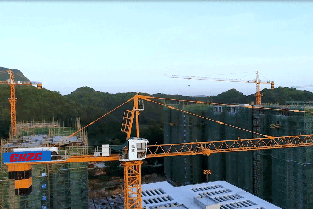
As critical equipment in construction projects, the installation quality of tower cranes directly impacts project progress and construction safety. This document systematically outlines the installation process and technical essentials using self-erecting tower cranes as an example, providing standardized reference for on-site operations.
I. Tower Crane Pre-Installation Preparation
Site Planning
Determine installation height and jib length based on crane model, calculating required standard section quantities and counterweight weights. For example, a 45-meter jib crane requires six 2.1-ton counterweights. The installation area must be leveled and compacted, with bearing capacity exceeding 25 tons per square meter to prevent overturn risks from ground settlement.
Equipment Inspection
Conduct pre-inspection of critical components including the hydraulic jacking system, high-strength bolts, and pins. Hydraulic oil must meet specifications: 10W aviation oil for winter or 20W oil for summer, with oil levels maintained above 2/3 of the gauge. All bolts must achieve design preload torques (e.g., M30 bolts require 1800 N·m).
Personnel Configuration
The installation team must include two certified crane operators, two electricians, and two signalers, equipped with walkie-talkies and other communication devices. Establish a safety perimeter on-site, prohibiting unauthorized personnel from entering the 6-meter danger zone.
II. Tower Crane Main Structure Installation
Foundation Section Installation
Use a truck crane to lift the pre-assembled foundation section onto the embedded legs, connecting it with eight pins. Verticality shall be verified using a theodolite, with deviation controlled within 1.5‰. For example, vertical deviation for a 60-meter tower crane shall not exceed 90 millimeters.
Lifting Frame Assembly
Adjust the clearance between climbing frame guide wheels to 2-3 millimeters. Position hydraulic lifting cylinders on the same side as the tower body steps. During installation, ensure climbing claws are fully engaged with the foundation section steps.
Slewing System Installation
Assemble the slewing bearing assembly on the ground, including upper/lower bearings, slewing mechanism, and operator cab. Connect the lower bearing to the standard section using high-strength bolts with a torque of 3200 N·m. Calibrate the slewing limiter to operate within ±540°.
Tower Top Installation
Pre-install the counterjib tie rods on both sides of the tower top, connecting them to the upper bearing via 4 pins. Note: The tilt direction of the tower top must align with the boom, with an error not exceeding 5°.
III. Tower Crane Boom System Installation
Balancing Arm Installation
Assemble the balancing arm assembly on the ground, including the hoisting mechanism, resistor box, and two tie rods. Lift using dual slings at four points, maintaining the boom's horizontal level. After positioning, connect to the upper bearing via pins, then raise to a 45° angle to install the tie rods.
Jib Installation
Assemble jib sections in sequence per manual, placing radius indicators every 10 meters. Use the luffing trolley for lifting. After connecting the jib root to the upper support, pull the tie rods using the main winch wire rope. For example, a 50-meter jib requires assembly in three sections; tie rod connections must have split pins fully inserted and opened.
Counterweight Installation
Select counterweight combinations based on boom length. For example, a 45-meter boom requires six counterweight blocks. Lift each block individually using specialized lifting gear, ensuring support pins are fully inserted into connection plate holes. Secure the final counterweight with locking pins after installation.
IV. Tower Crane Commissioning and Acceptance
Electrical System Inspection
Check insulation resistance for all circuits: power lines must not fall below 0.5MΩ, control lines must not fall below 1MΩ. Calibrate limit switches to ensure lifting height, slewing angle, and other parameters meet design specifications.
No-Load Trial Operation
Conduct separate tests for hoisting, slewing, and luffing mechanisms to verify braking reliability. For example, the braking distance of the hoisting mechanism under 1.25 times rated load must not exceed 100 millimeters.
Verticality Calibration
Use a laser plumb line to inspect tower verticality. Deviation must not exceed 4‰ at free-standing height and 2‰ after attachment installation.
V. Tower Crane Safety Precautions
Wind Speed Control
Installation must occur below 13 m/s wind speed. Wind speed during jacking must not exceed 8 m/s. Equip with an anemometer for real-time monitoring; halt operations immediately upon exceeding limits.
Operational Standards
During jacking, rotation, luffing, or hoisting operations are strictly prohibited. Maintain uniform clearance between the guide wheels and tower body. Secure the guide trolley after section addition to prevent slippage.
Emergency Management
Develop specialized emergency response plans and equip sites with first-aid kits, fire extinguishers, and other necessary equipment. Conduct regular drills to ensure personnel are proficient in handling emergencies such as falls from height and mechanical failures.
Tower crane installation must strictly follow the five-phase process: Preparation → Main Structure → Jib → Commissioning → Acceptance. Standardized operations and comprehensive process control effectively reduce installation risks and ensure construction safety. Statistics indicate that compliant installation reduces tower crane accident rates by over 70%, providing robust safeguards for engineering projects.


Connect
Get in touch for your project needs today.
Contact us
Email:ann@gkzgtowercrane.com
Tel/Whatsapp/Wechat:+86 13437895301
Copyright © 2025. Guangxi Gongkai Heavy Industry Manufacturing Co.,Ltd.All Right Reserved
Address: No.12 Fuqiao Avenue, Longan Overseas Chinese Administration District, Nanning, Guangxi,China